Pointerra Viewer Quick Start Guide
This guide outlines the basic functionality of the Pointerra 3D viewer.
Pointerra Viewer Quick Start GuideViewer Interface OverviewClear ModeFullscreen ModeHome ButtonControlling the CameraPointcloud Display OptionsScene OptionsDisplaying Coordinate InformationMoving the camera to plan viewChanging the Background ColourMap OptionsDisplaying the Point Cloud over a Base MapUsing the Tools Point of Interest Tool
 Line Measure Tool
 Horizontal Crop Tool
 Vertical Crop ToolExtracting and Exporting Part of a Point CloudSelect the area of interest
Viewer Interface Overview
The main elements of the user interface for the viewer are highlighted in the image below. Clicking on the Options icon will allow you to access various settings for configuring the display of the point cloud and the viewer.
Depending on the type of data being displayed, the Left Panel will display additional configurations options. These are specific to the point cloud being viewed, and include controls for configuring the display and filtering of point-types for classified point clouds, and layer controls for point clouds that have multiple scans or layers. The top section of the Left Panel also contains the Tools Palette, that contains various tools for interacting with the point cloud data. The Left Panel can be collapsed and restored by using the small arrow icon at the top-right of the Left Panel.
A 2D Overview Map displays a top-down view of the point cloud in conjunction with configurable base map layers. There is a separate tool palette that allows for some functions (e.g. cropping, sections) to be initiated directly from the map display. The map can be minimised, or maximised, using the arrow icons.
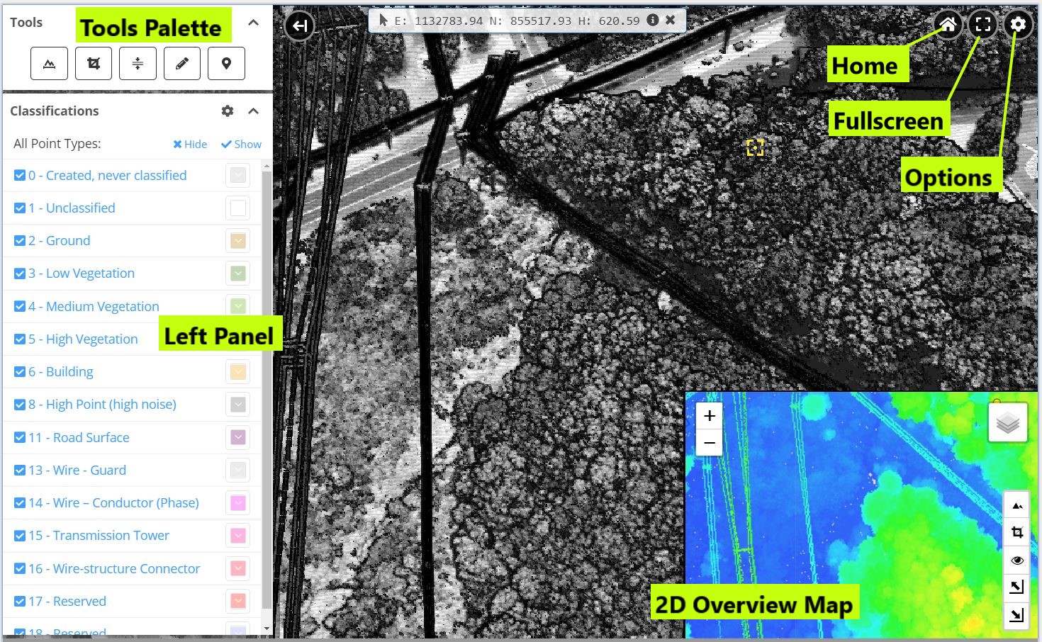
Clear Mode
You can quickly minimise all of the user interface elements by pressing the left square bracket key [ on your keyboard. This will temporarily hide most of the user interface controls, including the 2D map, so that you have maximum screen area for viewing the point cloud. You can restore the user interface elements to their previous state using the right square bracket key ]
Fullscreen Mode
Click the Fullscreen button to make the viewer take up the full area of the browser window. Click the button again to return to the previous viewing mode.
Home Button
Click the Home button to return the viewer to the last saved home position. This will typically be the initial view that the point cloud was in when it was loaded. You can press the H key to set a new home position for your current session.
Controlling the Camera
To change your view of the point cloud, you move a camera using either the mouse or keyboard controls. The primary way to navigate through the scene is to use your mouse (sometimes in combination with keyboard modifiers).
You will notice a small yellow marker  tracks your cursor as you move it around the scene. The center of this marker indicates the currently selected point within the point cloud. For most operations the selected point will determine the focus point for the movement (for example, the point to zoom in to, or the point to rotate about). The table below gives further details on the various movement options.
| Operation | Controls | Alternative | Description |
|---|---|---|---|
| Pan/Move | Drag with Left Mouse button | Use the W,A,S,D keys (Use SHIFT key to increase speed when using keys) | Move the mouse over a point and then click and drag to move the camera. This will have the sensation of moving the point cloud. |
| Zoom | Drag with Right Mouse button | Use Z key to quick zoom to highlighted point. Use SHIFT + Z to zoom out. Double-click mouse to zoom in. | Move the mouse over a point that you want to zoom toward (or away from) and drag using the right mouse button, or use the Z key. |
| Rotate | Drag with Middle Mouse button | Drag with Left Mouse Button while holding down the CTRL key | To rotate about the currently highlighted point, drag with the Middle Mouse button. This will move the camera around the highlighted point. |
| Up | E Key | Move the camera up (relative to the direction that it is currently pointing) | |
| Down | F Key | Move the camera down (relative to the direction that it is currently pointing) | |
| Look | Arrow Keys | Use SHIFT key to increase speed | Change the direction that the camera is looking without moving the camera |
Pointcloud Display Options
Click on the Options button and select the Points tab to view the various options for adjusting the display of the pointcloud. The main options are described in the table below.
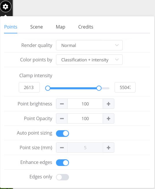
| Menu Option | Keyboard Shortcuts | Description |
|---|---|---|
| Colour Points by | none | Determine how the points are coloured. The options that are available in the list will depend on what properties are present in the original data. |
| Auto Point Sizing | none | If checked, the viewer will try to automatically determine the best size to display points. The point size may dynamically change as different parts of the point cloud are viewed. |
| Point Size (mm) | K,L | If not using auto-sizing, you can specify the exact size (in mm) to render points in the scene. You will often want this to reflect the underlying point spacing of the data (i.e. scans with large point spacing/density will draw with larger point sizes) to fill in gaps between points. |
| Point Opacity (%) | none | Adjust the opacity of the points. Reduce opacity to enable viewing basemaps and other data layers that are behind the point cloud. |
| Point Brightness | none | Adjust the percentage brightness of the point display. |
| Render Quality | 4,5,6,7 | This setting allows you to trade off display quality with the amount of data that needs to be sent over the network. If you are on a slow network, you should use one of the lower settings to maintain an interactive experience. Once you have the view set to an area of interest, you can then increase the quality if desired. |
| Enhance Edges | none | The renderer uses depth information to enhance the definition of edge features in the point cloud. You will generally want to turn this on to get a better visualisation of the points. |
Scene Options
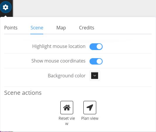
The Scene tab has options that are not directly related to the point cloud display. The most commonly used options are described below.
Displaying Coordinate Information
The coordinates of the currently highlighted point can be displayed by enabling Show mouse coordinates from the Scene menu. The coordinates are displayed in the coordinate reference system that the data was captured in and the value is dynamically updated as the mouse is moved around the scene. You can get detailed information about the coordinate system from the tooltip that will appear when you hover your mouse over the info icon. Pressing the 8 key will toggle display of coordinates.
Moving the camera to plan view
You can move the viewer into a top-down map/plan view (with North up) by clicking the Plan view button from the Scene tab. This can be useful for selecting cropping areas and other specific tasks that require a top-down view. The scene will still be in full 3D control mode, so rotating the view will take you out of the 2D view.
Changing the Background Colour
If you want to change the background colour of the viewer window, use the Background Color colour picker to set the desired colour.
Map Options
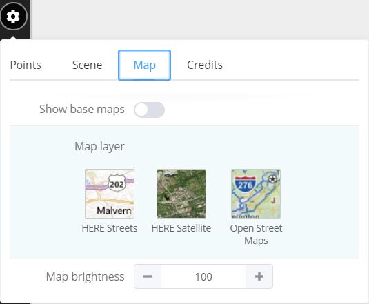
The Map tab has options for controlling the display of base maps in the 3D viewing window. This tab will only be shown if the point cloud that you are viewing is georeferenced.
Displaying the Point Cloud over a Base Map
You can choose to overlay the point cloud on top of a base map to give additional context to its location. There are a number of built-in base map layers including satellite imagery and street maps. To turn on display of a base map, turn on the Show base maps toggle. You can click on the icon of the map you would like to display to change the layer type.
NOTE: If you are under the terrain (or close to it) the base map will automatically hide. It may therefore be necessary to zoom out to get the base map displayed.
The B Key can also be used as a quick way to toggle the base map display on/off.
Using the Tools

There are a number of tools that allow you to make measurements on the point cloud. These are accessed from the top of the Left Panel. You can continue to manipulate your view while using the measure tools - the viewer will automatically determine if you are clicking on a measurement or trying to adjust the camera view.
 Point of Interest Tool
The point of interest tool allows you to create or edit point annotations containing some text and an optional hyperlink. After activating the POI tool, click with the Left Mouse on the desired point to create a new POI at the current mouse coordinate. A dialog box will pop up that allows you to edit the various properties of the POI. Once you click Close, the data will be saved to the Pointerra database so that the POI can be reloaded next time the point cloud is viewed. Either the name, or the coordinate of the point (if the name is left blank) will be displayed if you hover your mouse over the POI marker.
You can move a POI to a new location by activating the POI tool and then holding down the SHIFT key while dragging the marker to a new location. The updated location will automatically be saved.
You can edit a POI by clicking on the POI's marker. This will display the edit POI dialog. You can also delete the POI from this dialog.
You can activate the POI tool by pressing the V key in the viewer.
You can toggle the display of POIs in the scene from the POI panel that will appear in the Left Panel when there are POIs in the scene. This does not delete the POIs, it will just show/hide them.
NOTE: The POI tool will be disabled if you do not have permissions to edit POIs for the point cloud that your are viewing. You will still be able to view the POI data, but will not be able to edit or delete. POIs
 Line Measure Tool
The line measure tool calculates the 3D distance between a set of points that you select. After selecting the line measure tool, click on points to make measurements - a coordinate info marker will be created at each of the points that you click. You can see corresponding information about each coordinate, including the total line length, in the Line Measure Dialog that will popup on the right hand side of the viewer.
In addition to displaying the cumulative distance along the path, each coordinate info marker also displays the difference in height from the first marker, displayed as "dH(0)". You can use this to perform vertical measurements by placing the first point of the measurement line on your zero reference point (often the ground), and then creating a second point to measure the 3D distance and the height difference. If you move the marker (see below), the measurements will interactively update. You can therefore use this to interactively measure the difference between a reference point and any other point in the scene.
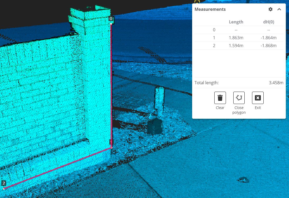
To adjust an individual marker within a measurement that you have already created, simply click on the marker again and the when you move the mouse, the location of the marker will adjust to the newly selected point. As you move the mouse close to an existing measurement marker, you will notice that the cursor position indicator snaps to the existing marker - this will give you a visual cue that you are about to adjust the marker position.
| Keyboard Shortcut | Description |
|---|---|
| Backspace | Delete last point |
| Enter | Close line (if more than 2 points) |
| + | Increase line width |
| - | Decrease line width |
| C | Clear all data |
| M | Exit line measure mode |
As you are selecting points from a 2D view of a 3D scene, it is possible that you will not select the point that you expected (you might select a point in the distance). During point selection, the viewer will always attempt to pick the point closest to the camera when there is ambiguity. However this is not a failsafe selection process. After creating a measurement, you should move the camera to a new vantage point to confirm that you have selected the correct points.
To delete the measurements, click on the Clear button, or press the C key on the keyboard. Use the Exit button to close the measurements dialog and exit measuring mode.
You can also use the M key to quickly toggle in and out of measurement mode.
 Horizontal Crop Tool
The horizontal crop tool lets you define a cropping area (in the horizontal/ground plane). Once defined, the viewer will only display the points that lie within the defined cropping area. This tool can be used to cut away parts of the point cloud and focus on a specific area. It is also used as a point selection tool for other functions, such as exporting a section of the point cloud.
You define the cropping box by clicking 3 points. Click the first 2 points to define one side of the box, and then drag the "rubber-banded" box to the desired size and click a 3rd time to finish. As you are defining a box parallel to the horizontal plane, you may find it more intuitive to place the viewer into a top-down view before defining the cropping box.
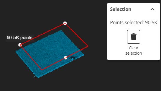
If you need to modify the cropping box, drag the manipulator handles (the white circles will turn green as you hover over them to indicate that they can be dragged) on the cropping box to adjust the position of the cropping area.
You can deactivate the cropping area tool by deselecting the tool from the toolbar. This will leave the cropping as you have set it, but return your mouse controls to camera move mode. You can reset (clear) and deactivate the cropping by pressing the Clear Selection button.
 Vertical Crop Tool
The vertical crop tool lets you crop the display of the points based upon a minimum or maximum height value (or both). Points outside of the defined point range will be cropped from the view. This tool is particularly useful for "looking inside" buildings by cropping away the roof - this allows you to navigate around in scans where both the inside and outside of a building have been captured.
To define the height cropping range, activate the vertical crop tool from the toolbar. You can use the left mouse button to click on a point in the pointcloud and set the height of that point as the maximum height for cropping. You can use the right mouse button to click on a point in the pointcloud and set the height of that point as the minimum height for cropping.
As you define the points, the manipulator for the tool will show handles with the selected height values displayed. You can drag these handles to adjust the height cutoffs (the handles will turn green as you move the mouse over them to indicate that you can move them). While the tool is activate, you can also redefine the cutoff values by simply clicking on new points from the pointcloud with the left or right mouse buttons. The manipulator will relocate to the newly selected points.
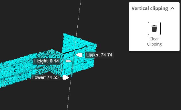
You can deactivate the cropping tool by deselecting the tool from the toolbar. You can *reset (clear) * the cropping limits while the tool is active by pressing the Escape key (you can also do this while you are defining the cropping limits if you want to start again). You can also reset the cropping at any time by clicking on the Clear Clipping rubbish bin icon in the Vertical clipping tool dialog.
Extracting and Exporting Part of a Point Cloud
You can extract a section of a point cloud (assuming you have the require permissions) into a file that you can download. The file formats that are currently supported for exporting are: LAS, LAZ, PTS. In order to enable the export function, you first need to select the area of interest.
Select the area of interest
Use the Horizontal Cropping Tool to select a region of interest from the point cloud. You can also further refine the selection with the Vertical Cropping Tool if desired. Once you have selected the desired set of points (adjust the selection using the tool as required), the viewer will crop the points outside of your selection, and will display the number of points selected.